We decided to put Kitty
to work on the project. We sent her off to Lowe’s in Abbeville to
find some spacers, or locate some nylon tubing of the proper size.
While Kitty was off trying to find material for the spacers, we got
back to the assembly of the OpenROV
kit.
We started on step #8,
Assembling
the Topside Tether Adapter updated 5/13/13. . We
were getting smarter between yesterday and today, so we watched the
video in it’s entirety, before attempting the assembly. We learned
two things by watching the video. First thing was, we were missing a
part to complete the assembly of the topside tether adapter. Second
thing was, we could complete the electronic assembly without the
topside tether adapter being together. Obviously to complete step #8
completely, we will need the missing piece.
The topside tether
adapter is being built from commercial off the shelf parts. The main
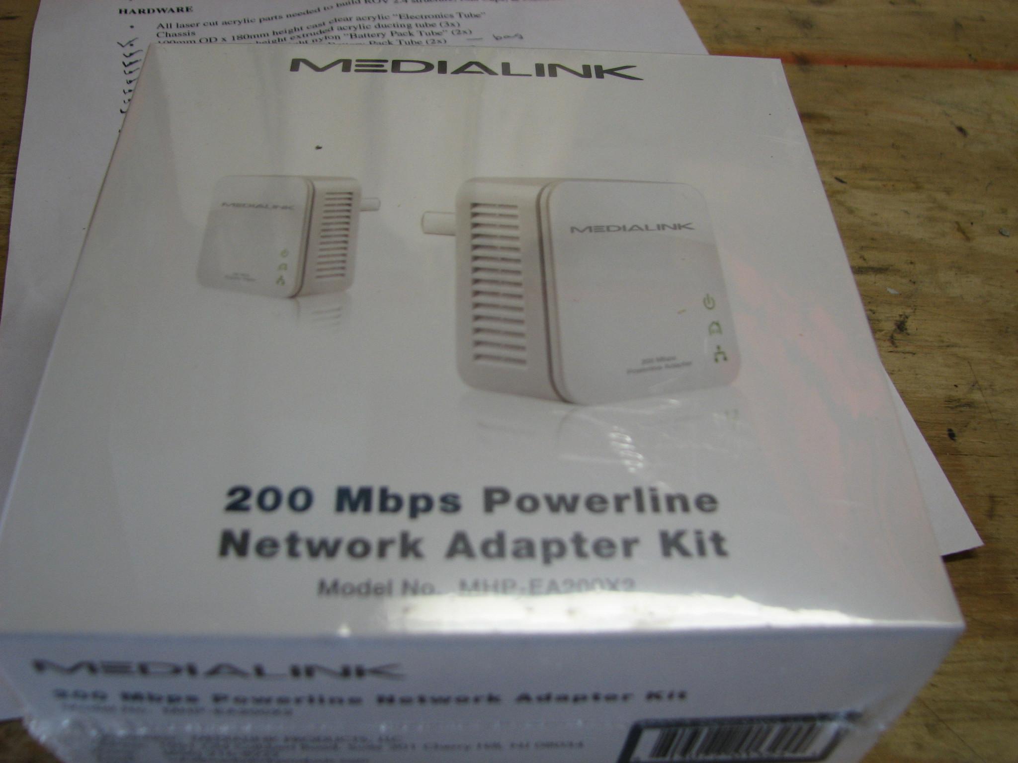
part being used is the Medialink
200 Mbps Powerline Network Adapter.
This is a device that uses the electrical wiring in a house to link
up with a wired Ethernet cable. We are going to use the half of the
electronics that convert the Ethernet signals to a two wire signal.
The half of the electronics that converts the two wire signal to 120
VAC we will not use.
As per the video,
Assembling
the Topside Tether Adapter,
we cut the tabs holding the halves together. We then discarded the
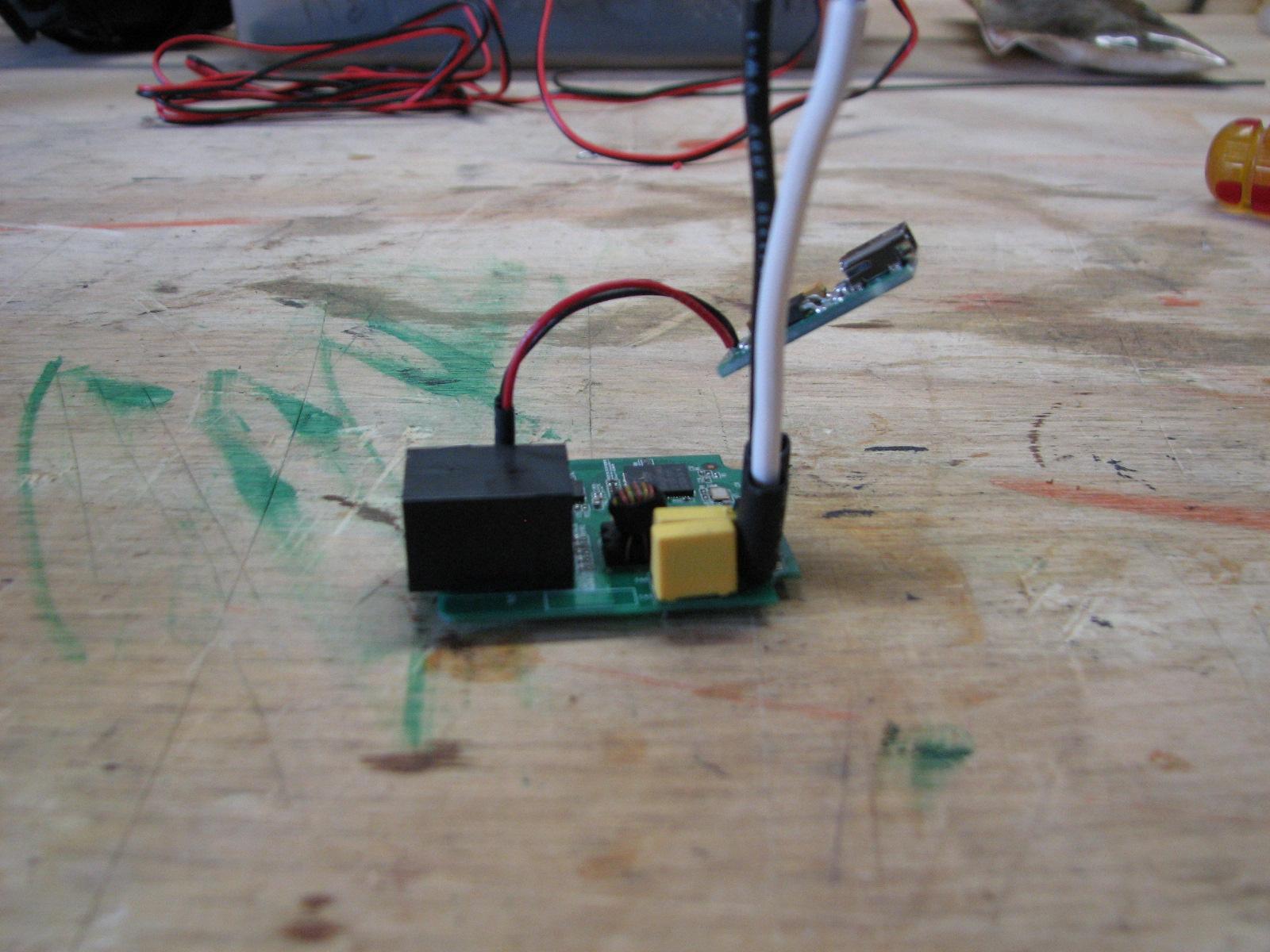
half not needed. We then soldered onto the remaining piece the USB
regulator board. This was
as far as we could get on this step. When we get the missing plastic
piece, we will complete this step.
Finished Tether Adapter
With USB Regulator
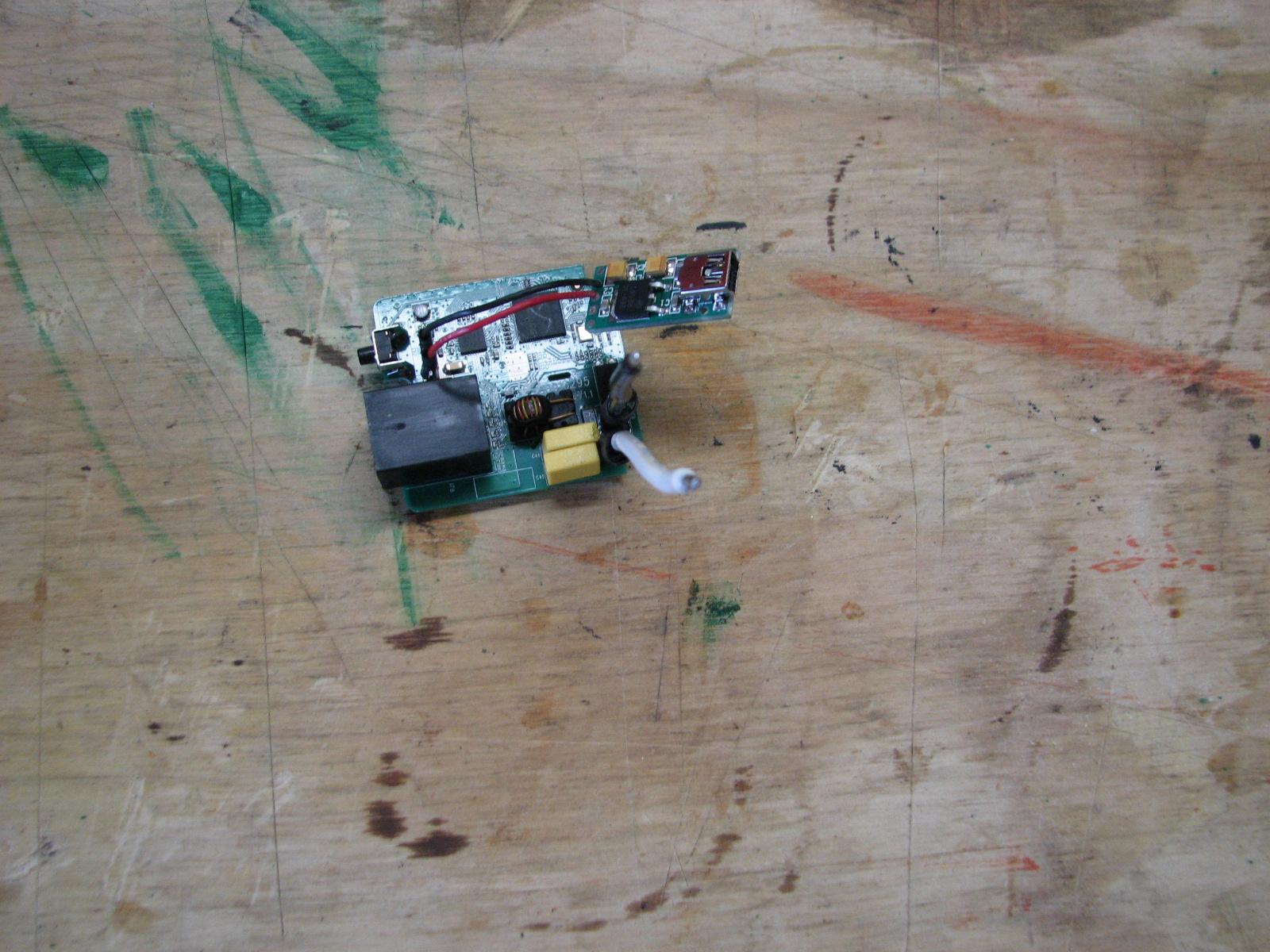
Finished Tether Adapter
With USB Regulator
We realized we did not
finish Item #7, Assembling
and Waterproofing the Thrusters,
so we went back and finished the phase for which we had the parts.
This phase had us remove the wire leads on the three motors, and
replace the leads with longer wires.
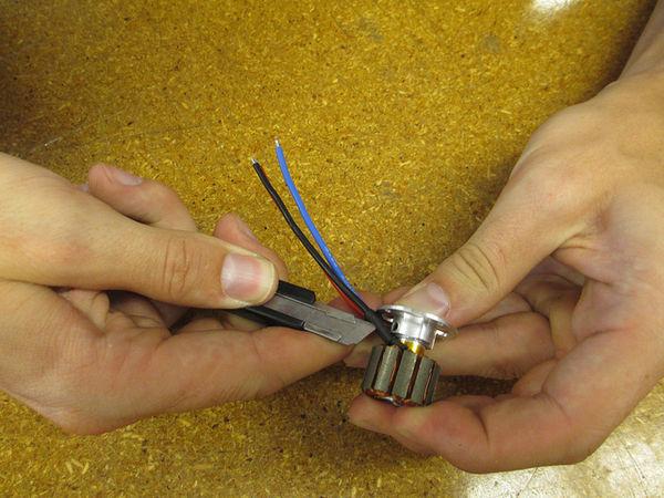
The key here is using a
very sharp safety razor blade, and to be very careful. There is a
single piece of shrink wrap that had to be cut off of the three wires
wrapped together. Then cut the shrink wrap off of each individual
wire.
Cutting Shrink Wrap Off
Of Wires
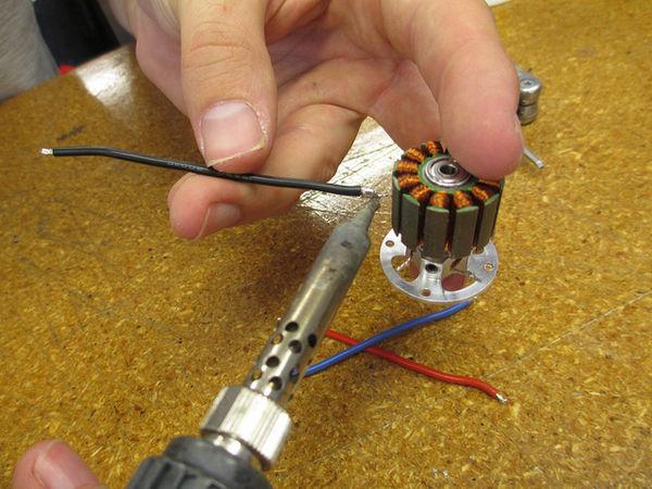
Then we had to unsolder
the wires off of each of the three motor leads.
Unsoldering Wires From
Motor Leads
Next was to cut the
necessary wire lengths to solder back on the motors. We cut and
striped the new wires, and then soldered the wire to the motor leads.
New Wires Soldered On
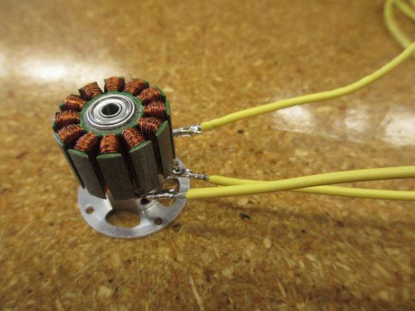
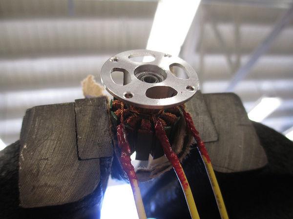
Now we applied the
liquid electrical tape, and reversed the sequence of installing the
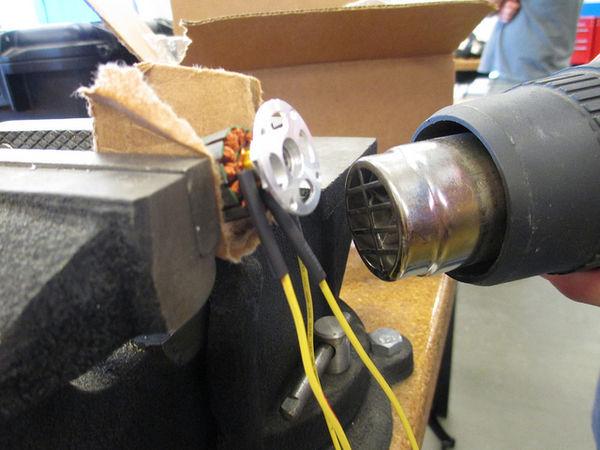
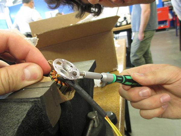
heat shrink tubing. We put an individual piece of heat shrink on each
wire, and when that was completed, put a single piece of heat shrink
over all three wires. This completes that phase of the Assembling
and Waterproofing the Thrusters.
Applying The Liquid
Electrical Tape
Heat Shrink On The
Individual Wires
Heat Shrink The Three
Individual Wires
Next on the assembly
instructions is step #9, Potting
the wire pass throughs in the end caps
v2.3 instructions only, v2.4 instructions will be updated soon. We
looked at the instructions, but since they were not the v2.4
instructions, we decided not to attempt it.
Now we went to step
#10, Programming
and calibrating the ESCs,
but we did not have a 12 VDC power source or any of the clip leads
required. These are a couple of more steps that need to be added to
the “Items NOT included in kit (that you will need)” list.
We skipped a couple of
steps, and moved to step #14, Assembling
the Internal Electronics Components
v2.3 instructions only, v2.4 instructions will be updated soon. When
we did this there were only v2.3 instructions, now they have the v2.4
instructions online.
At
the time we only had the 2.3 instructions, so we completed some of
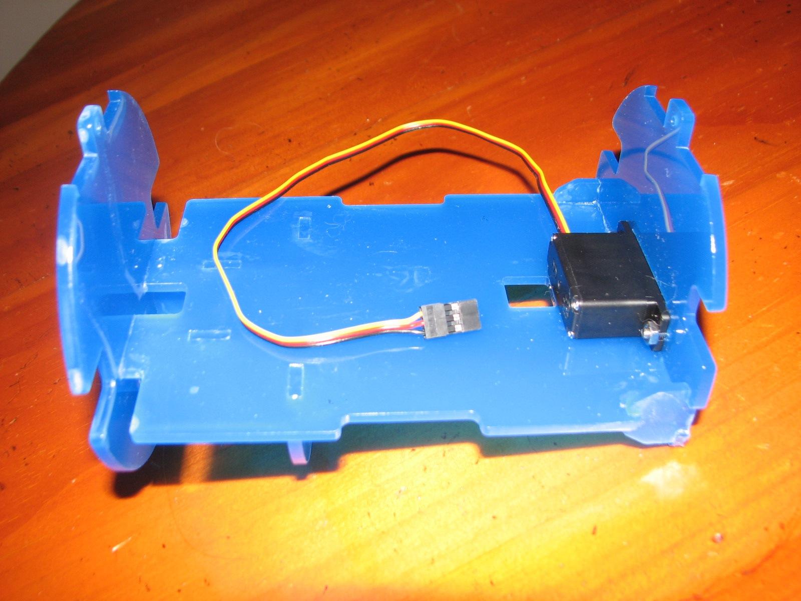
step #14. We looked at the first video, "Assembling
e-chassis structure", and completed that.
Complete
E-Chassis; Servo Attached
We
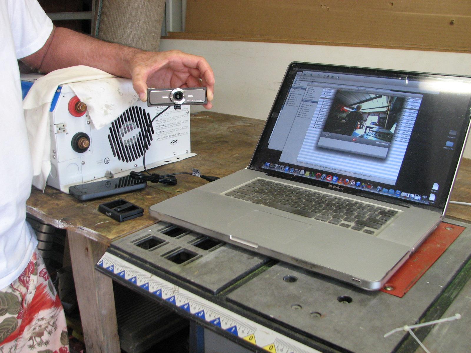
completed the second video, Electronics 1. In this phase we attached
the wide angle camera and the lights to its proper place. We first
unpacked the camera and checked it out on Stacy’s laptop. If you
look you will notice Stacy holding the camera, taking a picture of
me. I am showing up in a window on Stacy’s computer.
Wide
Angle Camera
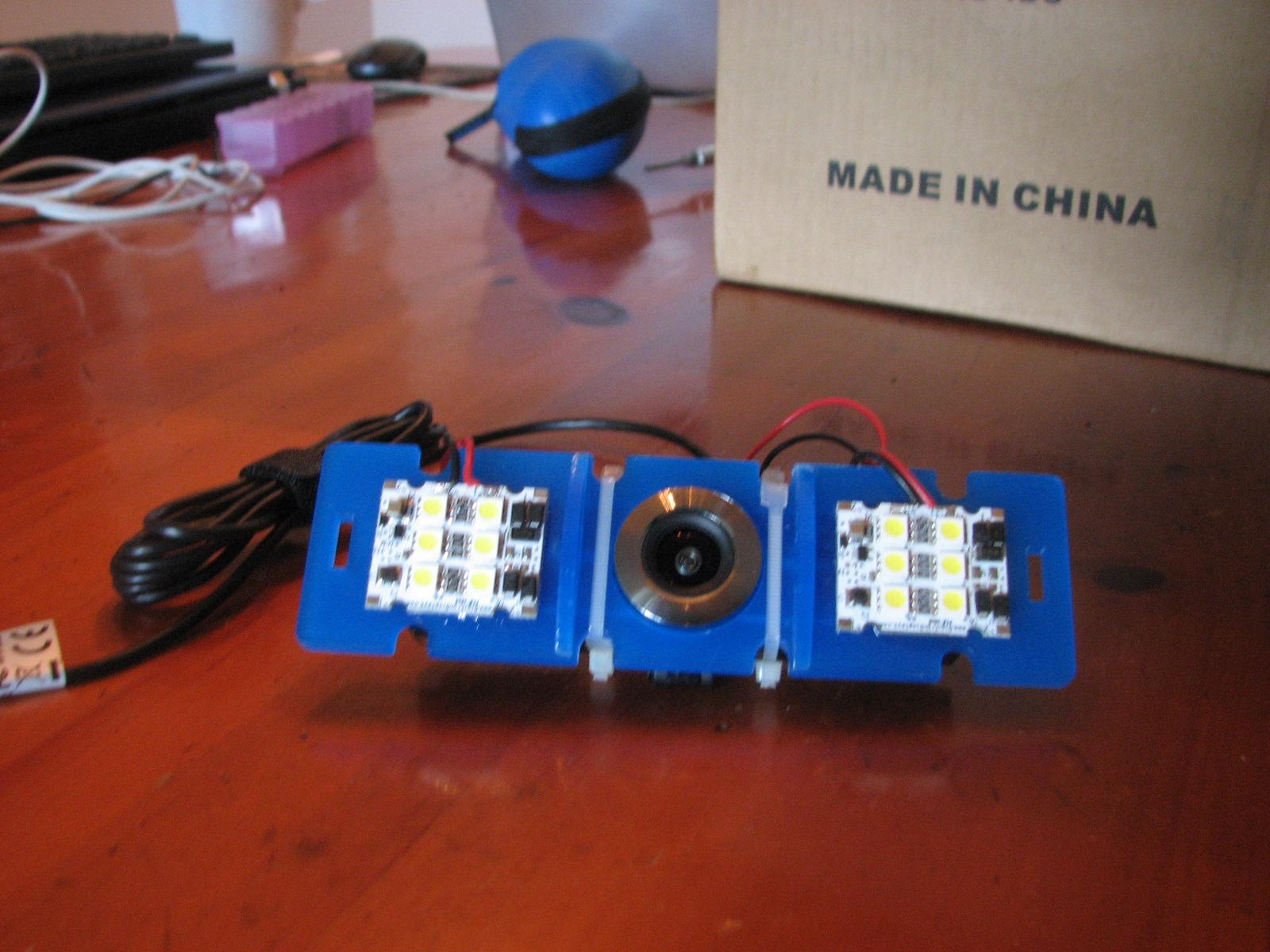
We
then installed the camera, since it had checked out good. I then
mixed up a bit of the 5 minute epoxy and glued the two powerful LED
lights to the camera housing. Obviously the lights are used to light
up what the camera is looking.
Camera
Housing With Lights Attached
When
we finished this phase, we decided to call it quits for the day. We
certainly got a lot accomplished. I had been over to DREAM AWAY three
times during the day getting parts and tools needed to continue.
We
still have a bunch to assemble and of course a couple of do overs,
but we can actually see the end of the tunnel. The really down side
is, it will be very difficult for me to get Stacy to Delcambre to help
finish the project, but we will see what is in the future.
May 25, 2013, Saturday
Stacy actually arrived
last evening, so we had time to do some preparation for the assembly
today. We downloaded all of the videos and hard copy (web pages),
that would take us through the assembly of the OpenROV
kit.
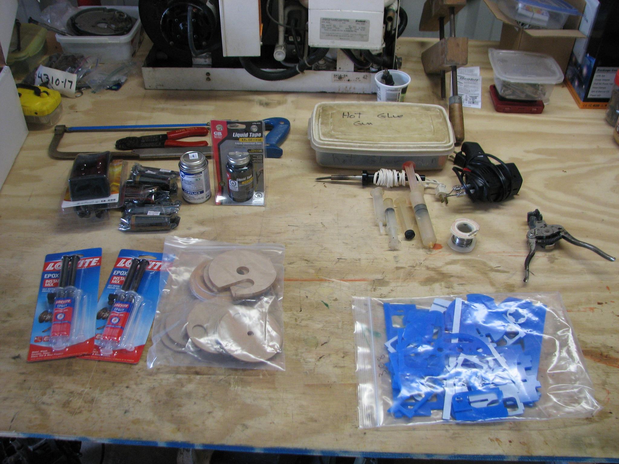
When we went to the
shop today, I had all of the required tools mentioned in the
documentation. We got out all of the parts purchased separately, and
the kit.
Parts And Tools Ready
For Assembly
Next we went to
geek-landia! Stacy and I got out our computers and I brought up the
following assembly instructions. Since we ordered the kit, we started
at step #4.
Step by step instructions
The OpenROV
consists of three parts: body, electronics and software, but most of
the work will go into assembling the body. But without further ado,
here is the list of steps:
1. What's
in the OpenROV Kit (only for those who bought the kit)
2. Cutting
out parts with laser (if
you have bought the kit you can skip to step 4)
3. Bending
the Outer Shell (if you
have bought the kit you can skip this step)
4. Assembling and Gluing the Inner Structure
updated 5/3/13
5. Assembling
and Gluing the end caps updated 5/4/13
6. Assembling
the Battery Packs updated 5/3/13
7. Assembling
and Waterproofing the Thrusters
updated 5/15/13
8. Assembling
the Topside Tether Adapter
updated 5/13/13
9. Potting
the wire pass throughs in the end caps
v2.3 instructions only, v2.4 instructions will be updated soon.
12. Install
the software for the
Beagle Bone and Cape(if you bought the kit, the BB image is already
in the SD, but the Arduino code needs to be uploaded)
13. Update
the software updated
5/3/13
14. Assembling
the Internal Electronics Components
v2.3 instructions only, v2.4 instructions will be updated soon.
15. Assembling
and sealing up the OpenROV
currently being updated
Read the
Software
Manual to know how to control the ROV.
Stacy would then bring
up the videos pertaining to the step we were assembling. As we
found out some steps have videos, and some steps just have a
web page with pictures.
Stacy Bringing Up A
Video
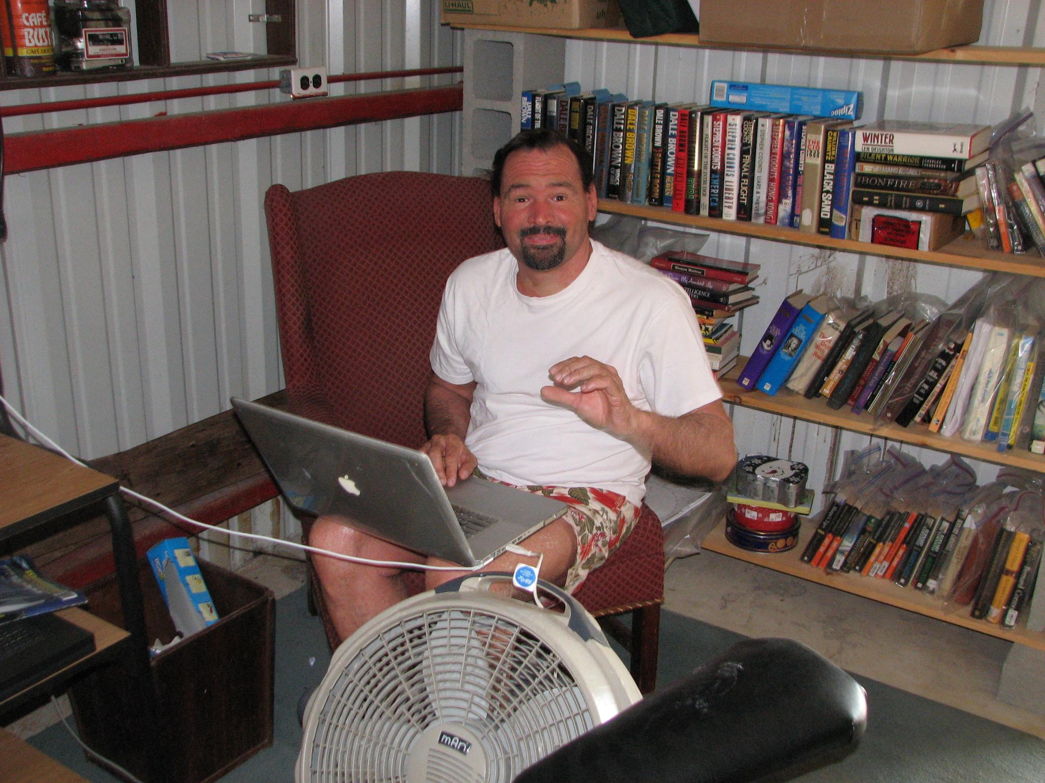
Let me just say here
that Stacy and I should have viewed and studied all of the videos and
web pages before we actually started the assembly. If we would have
done that, it would have been clear that the “Items NOT included in
kit (that you will need)” was not complete, and we could have done
an inventory of all of the “Acrylic Pieces needed to build the
kit”. So we were starting out behind the 8 ball, we just did not
know it at the time!
We started off with
step #4, Assembling
and Gluing the Inner Structure
updated 5/3/13. The
first thing we noticed when we brought up the video is we did not
have a syringe bottle. I had a couple of syringes I used with resins,
that worked just fine. It would have been nice if the syringe bottles
had been in the list of “Items NOT included in kit (that you will
need)”.
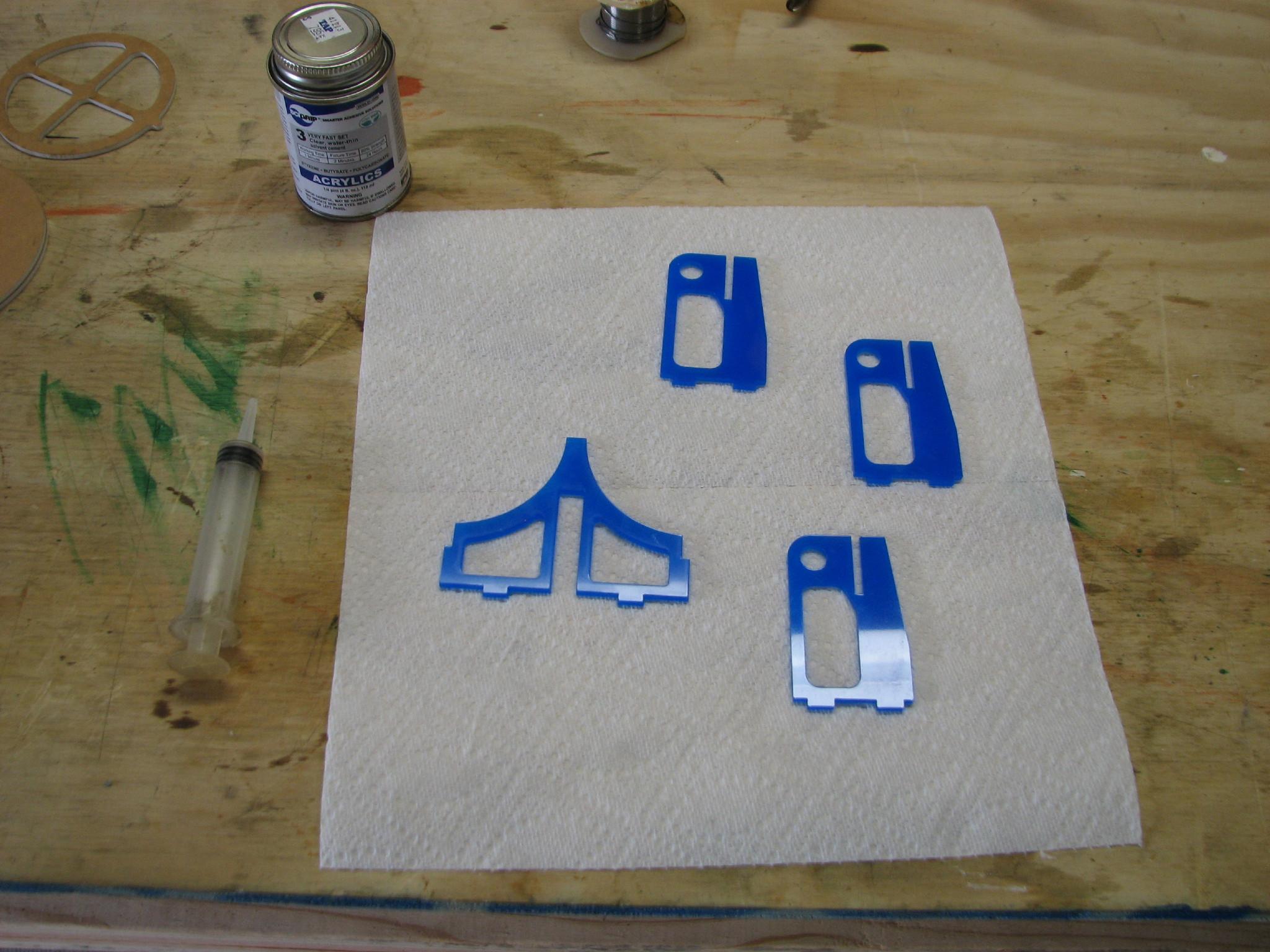
Step #4, Assembling and Gluing the Inner Structure,
was completed without too many problems. We did a dry fit of the
acrylic parts, and then we assembled them with the acrylic cement.
Inner Structure Pieces
Ready For Assembly
Stacy Assembling Inner
Structure
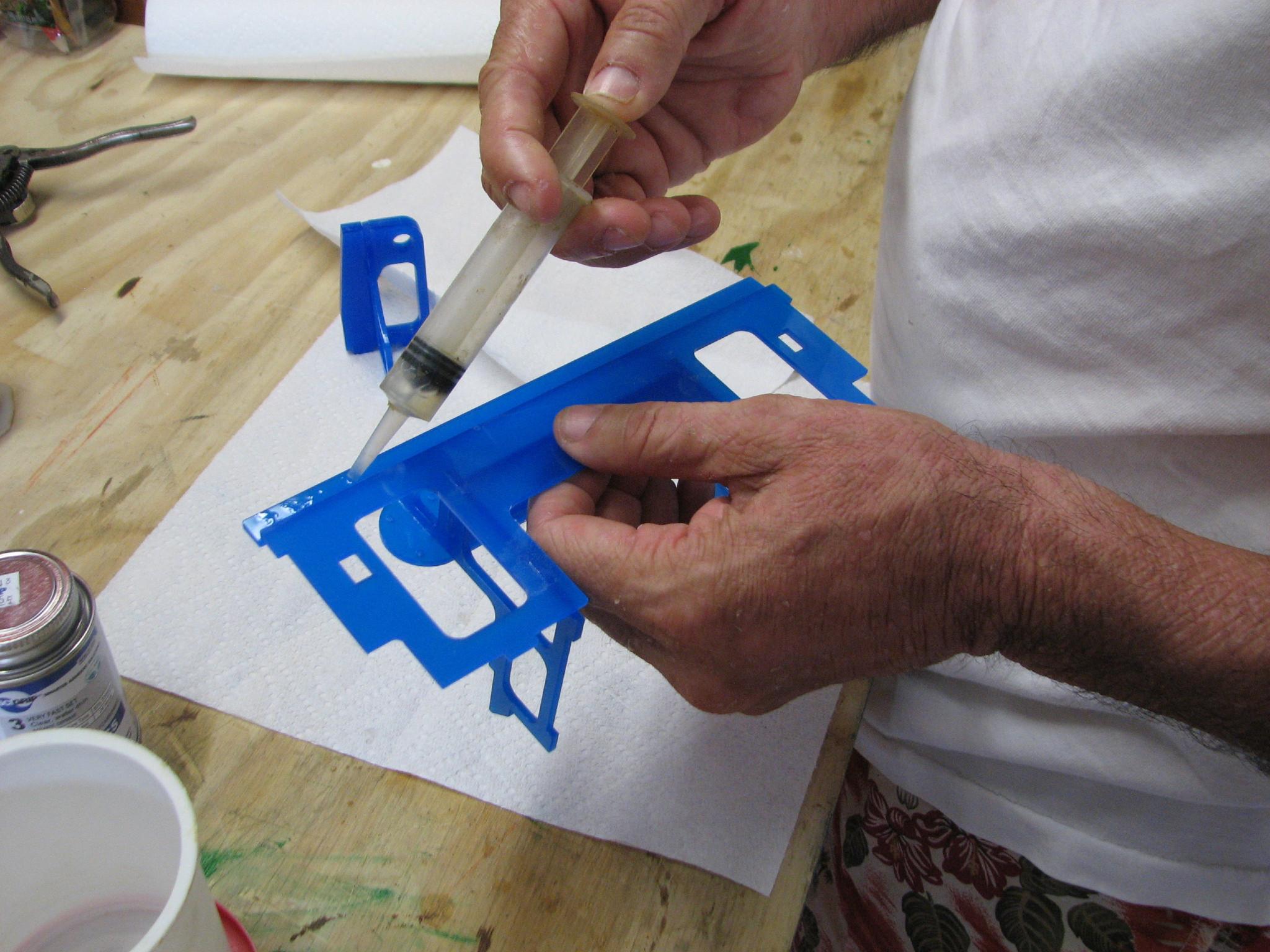
Stacy Assembling Inner
Structure

Jim Assembling Inner
Structure
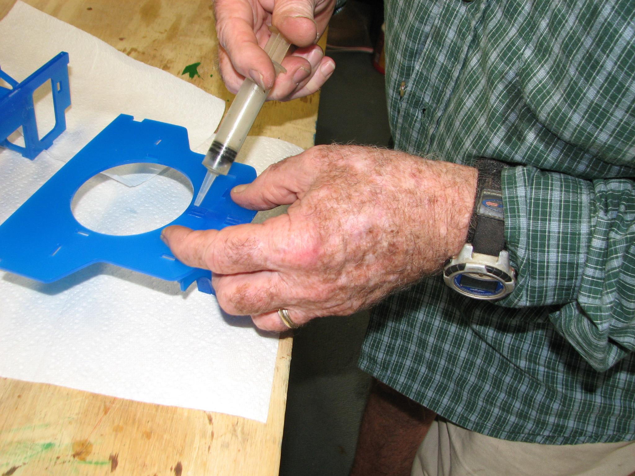
Stacy Assembling Inner
Structure
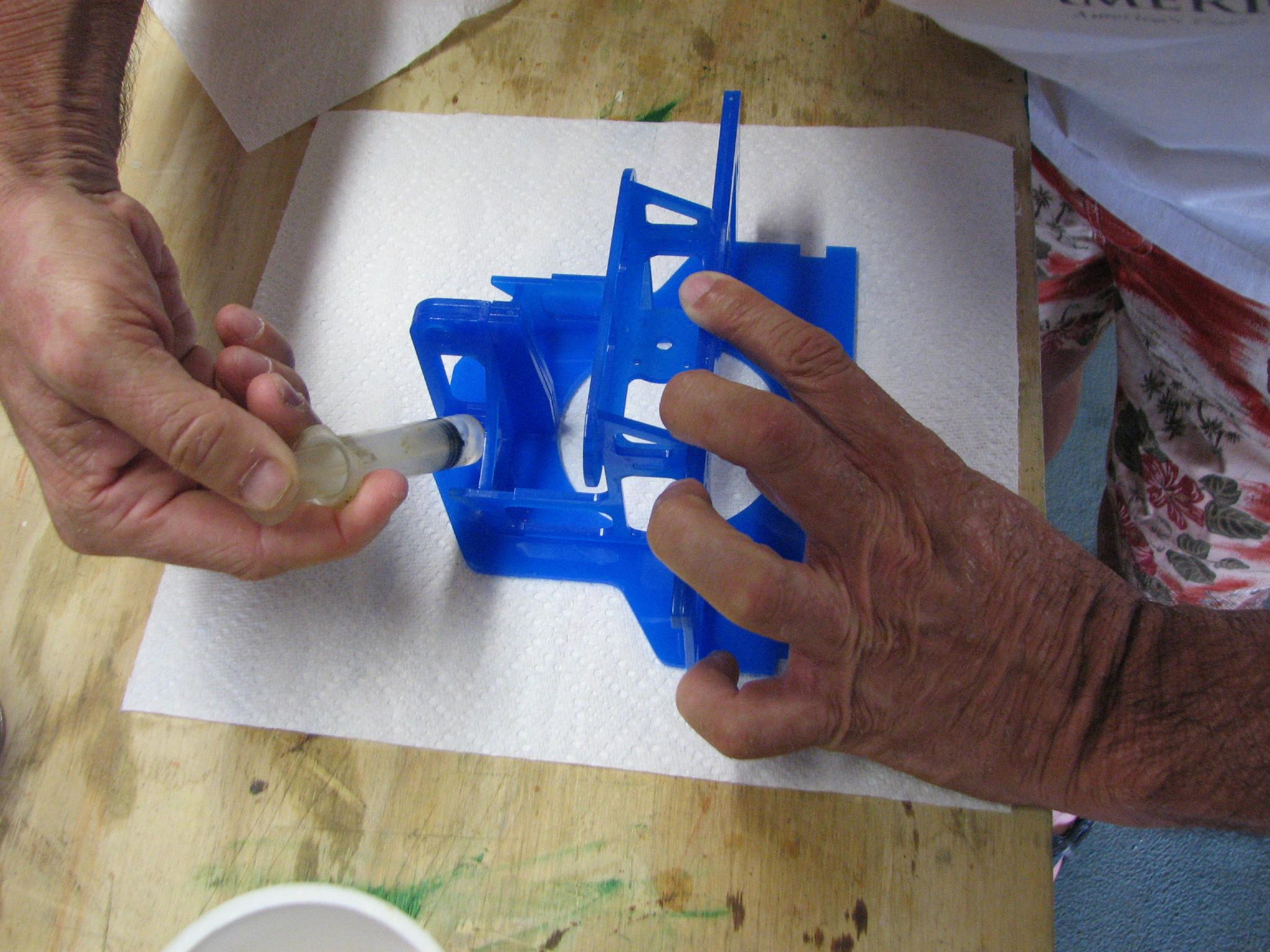
Completed Inner
Structure
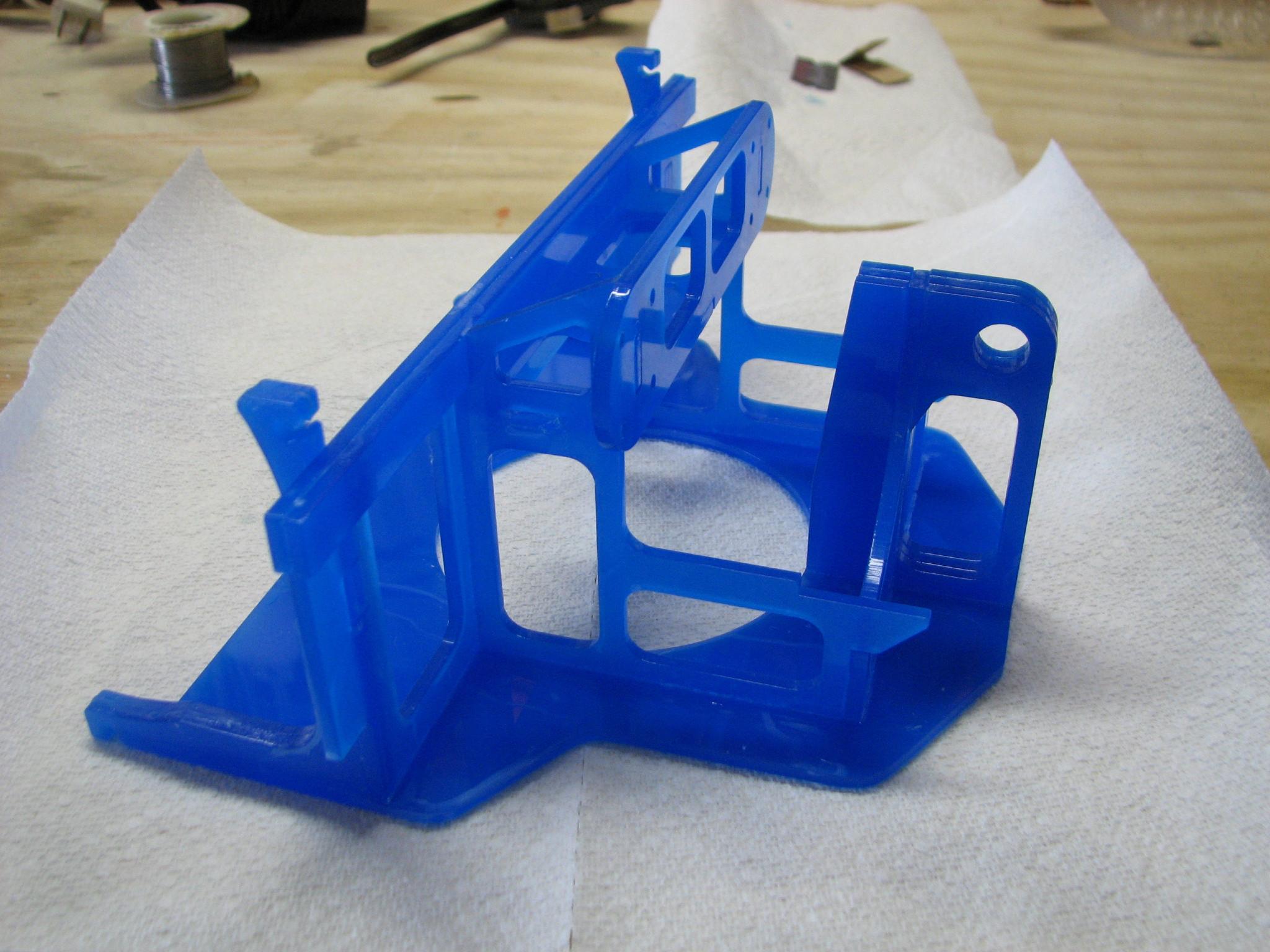
The #4 assembly step
went very well, so we were feeling pretty good about our progress.
Starting with step #5, Assembling
and Gluing the end caps
updated 5/4/13, things
started to go south.
In this step, we did
not view the video all the way to the end first. We would look at one
segment, get the required pieces for the assembly, and complete that
segment. We completed one of the end caps, and in the video it said
to make an exact copy, which we did. At the end of the video, it said
we should have made a mirror copy, and looking at the two end caps it
was obvious we needed a mirror copy, not an exact copy.
So Stacy and I had to
do some rework! We decided we were going to need new pieces to create
the second end cap again, it would not change anything to attempt to
take apart the “bad” end cap. We were lucky, and we were able to
get the end cap apart, and then back together as a mirror copy.
Another bit of bad news
here, I did not take as many pictures as I should have during this
process!
Cutting Parts For The
End Caps
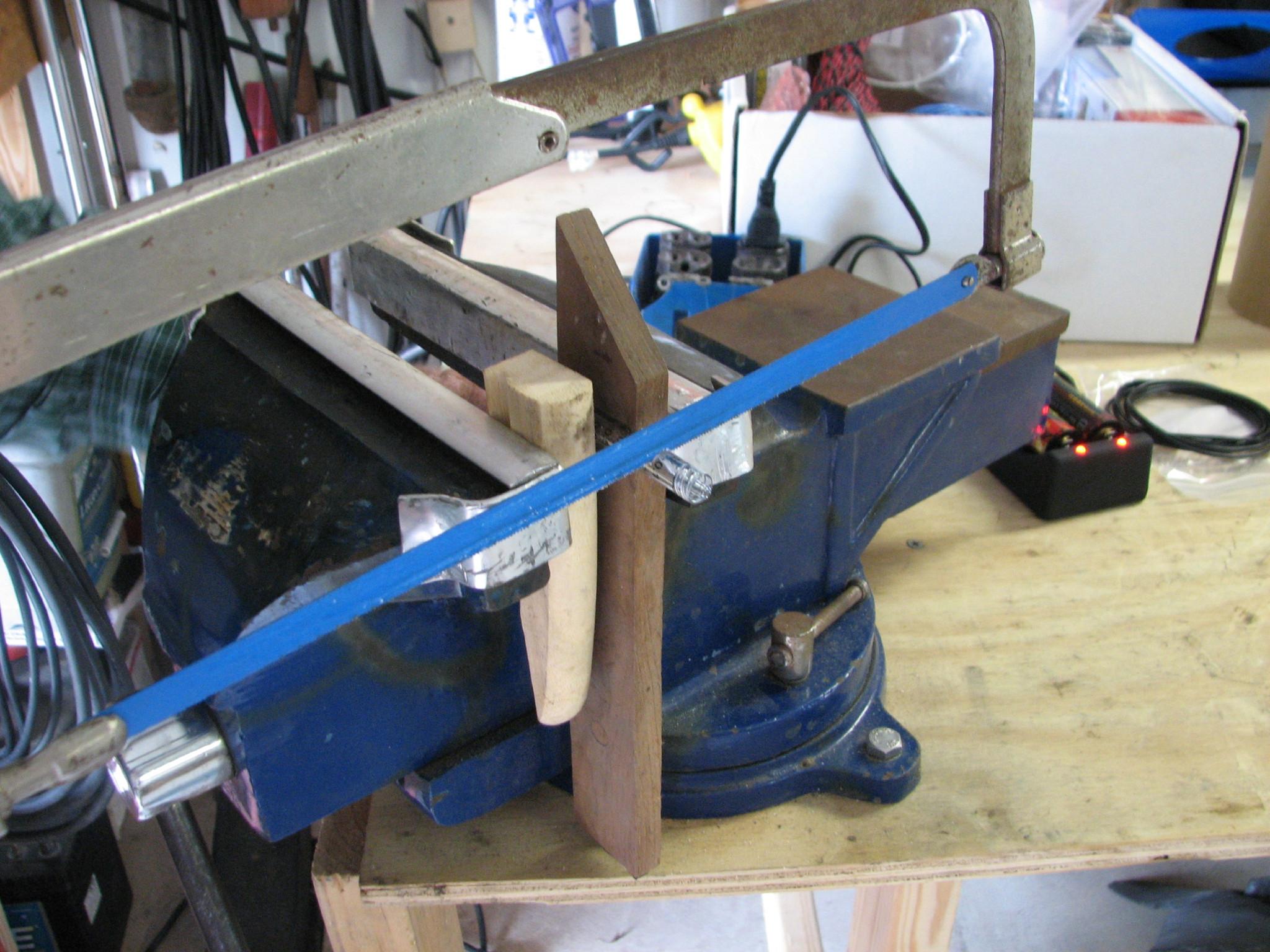
Jim At The Saw!
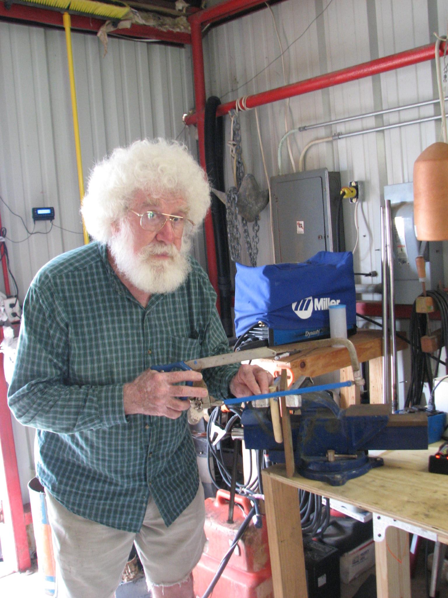
Finished “Mirror
Image” End Caps
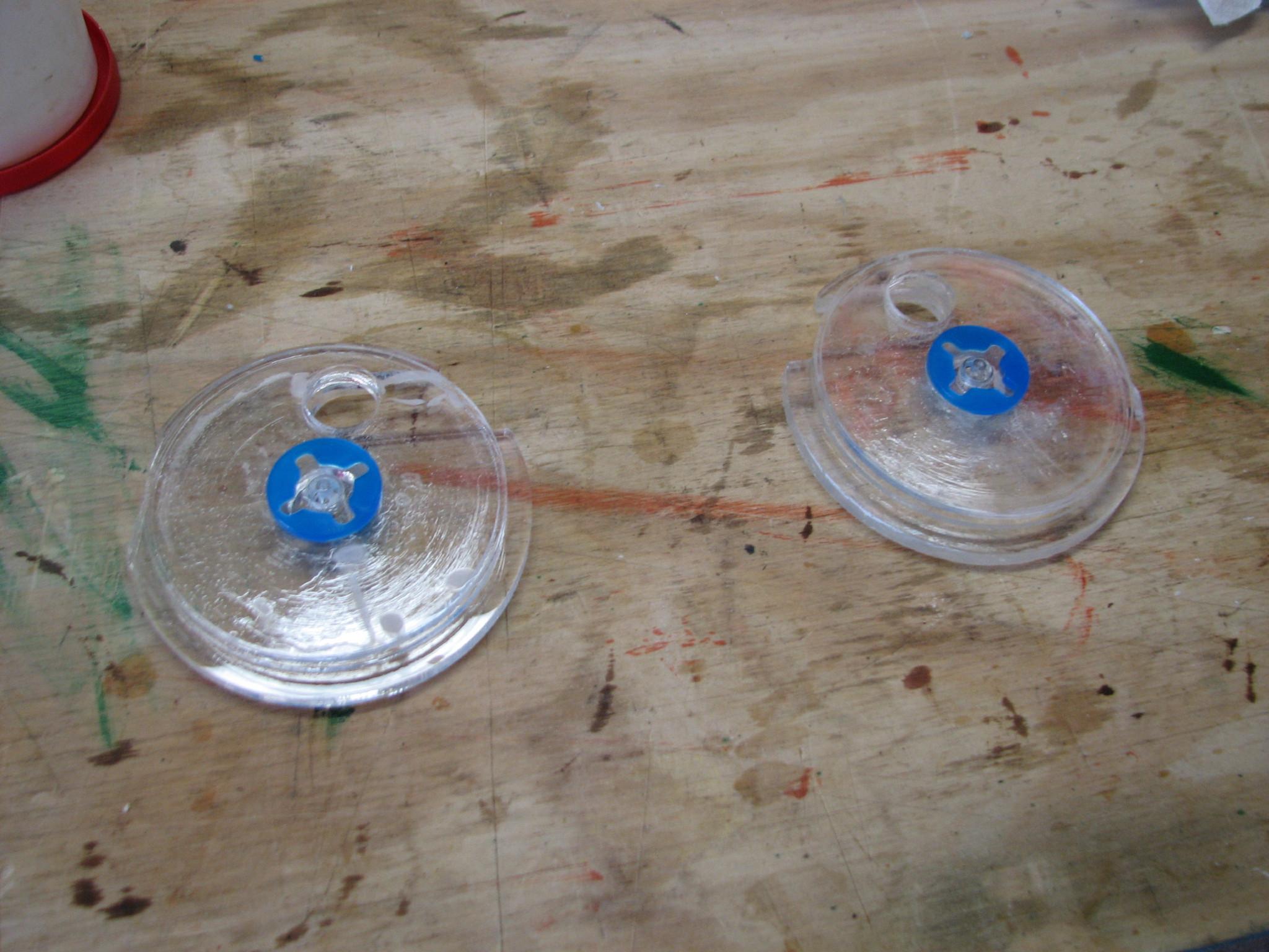
Now we got going on #6,
Assembling
the Battery Packs updated
5/3/13. Earlier in the morning, I had
unpacked the battery
charger and the
batteries,
and started the charging process. I was being optimistic that we
would need the batteries
before the day was over.
Here again, Stacy and I
caused ourselves problems because we did not read the "Changes
made between v2.3 to v2.4" section. In this section it
specifically states the battery connection has been changed from a
series battery connection to a parallel connection.
Stacy and I both
commented that wiring six 3.7
volt batteries in series
was going to equal a 24 volt power source instead of a 12 volt power
source. We actually went through the complete video, and there were
no changes in the assembly of the battery packs, so we decided to go
through the process as per the video.
The step #6,
Assembling
the Battery Packs updated
5/3/13 should be labeled V2.3, so we
would know there is a difference.
We assembled the
battery packs except for one change. They wanted us to seal the
battery packs with 5 minute epoxy, and we decided to use BoatLIFE
Life Seal. I felt this was
a better option because the epoxy is very brittle after it sets up.
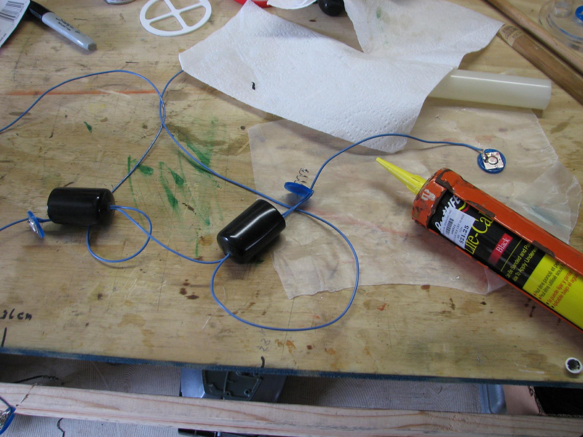
Battery Pack Under
Construction
Battery Packs BoatLIFE
Life Seal Applied
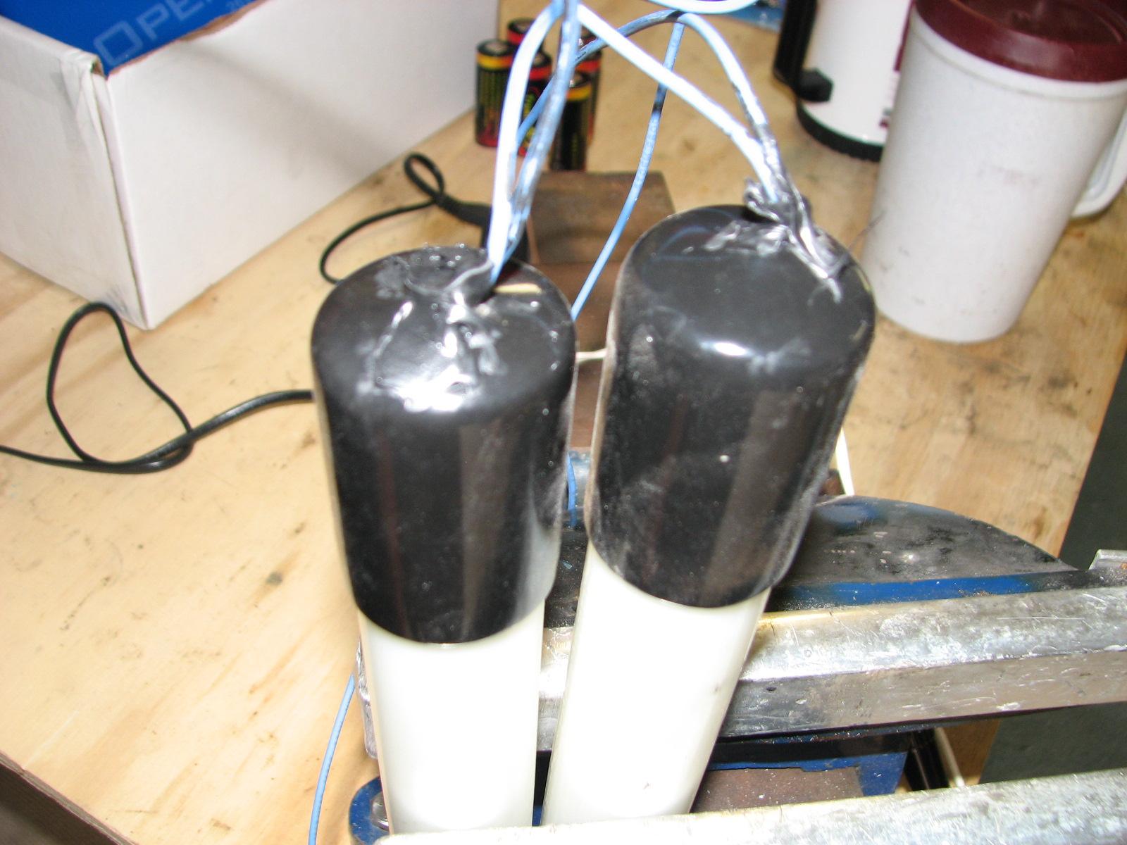
We set the battery pack
aside so the BoatLIFE
Life Seal could set up.
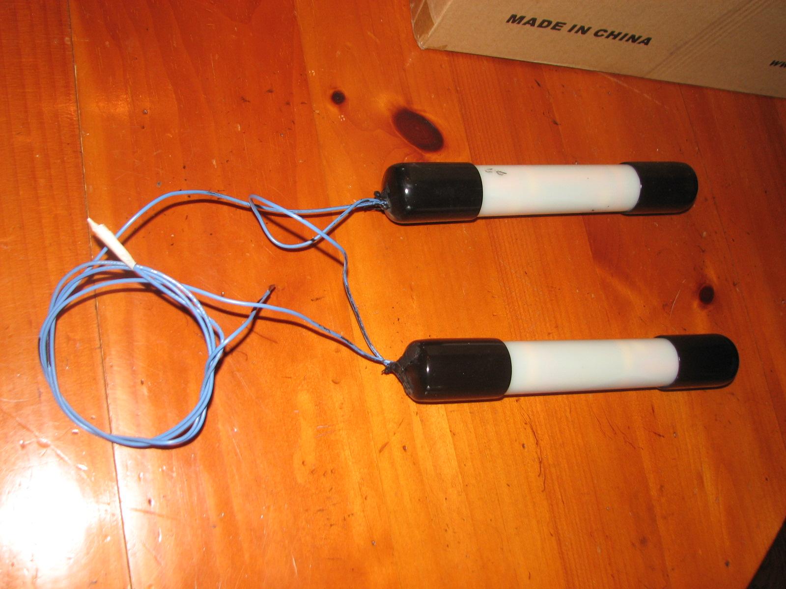
Completed Battery Packs
- Serial Connection
We then started on #7,
Assembling
and Waterproofing the Thrusters
updated 5/15/13, which
was very frustrating. The first picture shows someone using a tool
and removing the snap ring from the base of the motor (the snap ring
looks like a C).
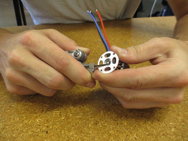
The very next picture,
they are moving right along. The snap rings on these motors are
incredibly small. I went back to DREAM AWAY, and brought my two sets
of snap rings pliers back to the shop. Both pair were way too big. It
was incredibly frustrating, and it took Stacy over an hour to get the
snap rings off of the shafts on the three motors. It would be nice if
the folks at OpenROV
would suggest or tell us what they used to remove the snap rings. By
this time we were ready to chew nails.
We skipped ahead in step #7 to the "Attaching
the Propellers to the Motor" phase.
In this phase we have to attach a propeller to the shaft of the motor
using a nylon spacer. The problem with this phase is we only had two
of the required spacers. These spacers were not part of the kit
inventory, and they should be! To add insult to injury, while
searching for the third spacer, we lost the second spacer!
Stacy and I spent the last hour of the day looking
for the lost spacers. We left the shop for the day a bit frustrated,
but very happy that we had got as far as we did. The OpenROV
was coming together. Stacy and I were taking notes so, as we move
along, we will be able to help the processes of the OpenROV
group with helpful suggestions.
May 21, 2013, Tuesday
All of the steps needed
not in the kit, I have on hand or have been ordered. the last two
steps that were ordered are supposed to arrive on Thursday, May 23rd.
All of the tools required for the kit assembly, I have on hand. So
come Saturday morning, May 25th, Stacy and I will be going to it!
A Couple Of Items
Purchased Locally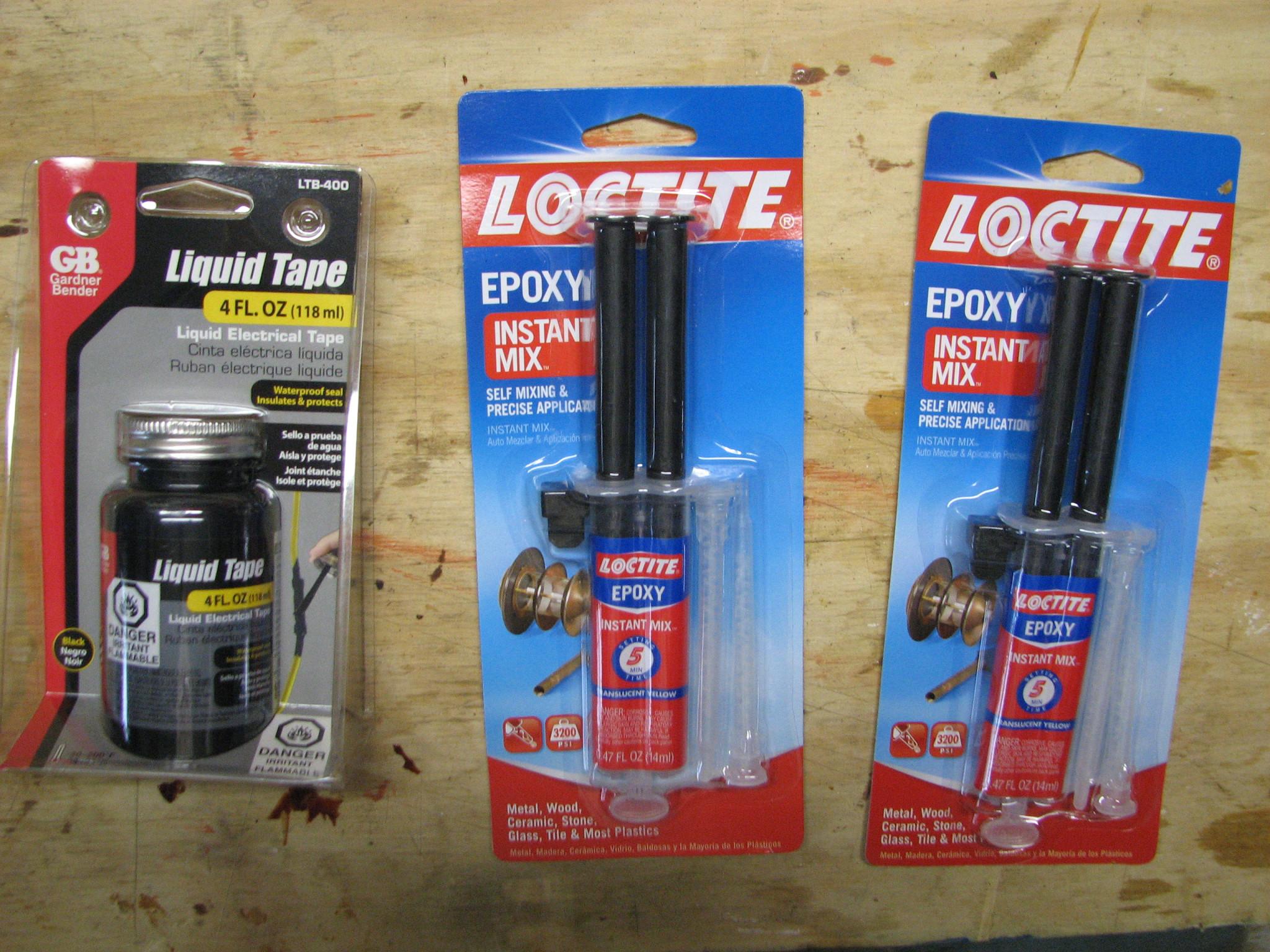

May 07, 2013, Tuesday
Today when I went over
to the shop, I had printed out the “What’s
In the OpenROV Kit”
inventory, so I would be able to do a proper inventory. The inventory
went very well. I was over on one part, and under on another part.
When I emailed the OpenROV
group, about missing a couple of M5 stainless nylon insert locknuts,
they told me the inventory should have listed four nuts instead of
eight. Now it turns out I have one extra nut, because I have five in
the inventory!
The first step on the
inventory says all of the necessary cut acrylic parts to assemble the
ROV 2.4 kit! That’s it! I do hope they are all there, because there
are very many of them!
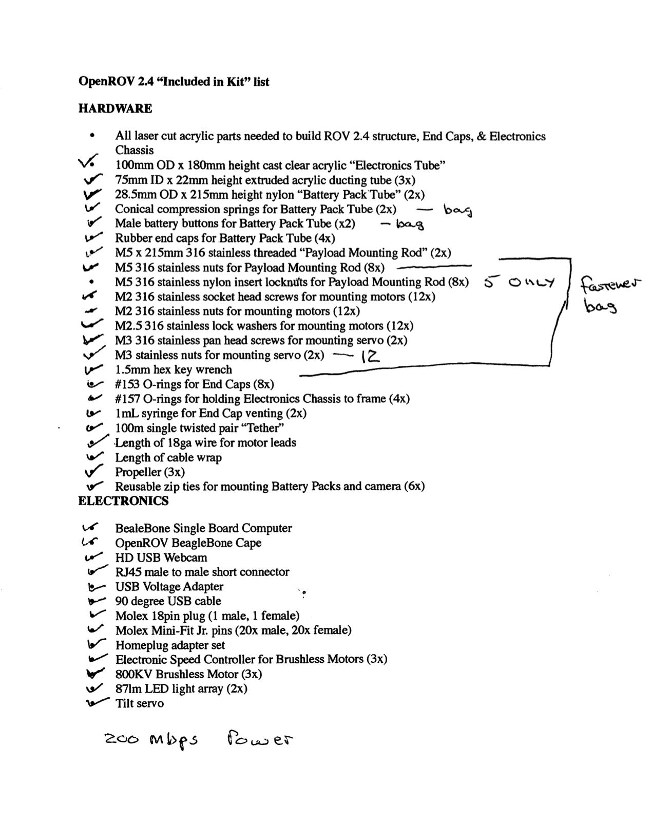
Following is the actual
inventory, and some photos of the parts during inventory.
Completed Inventory
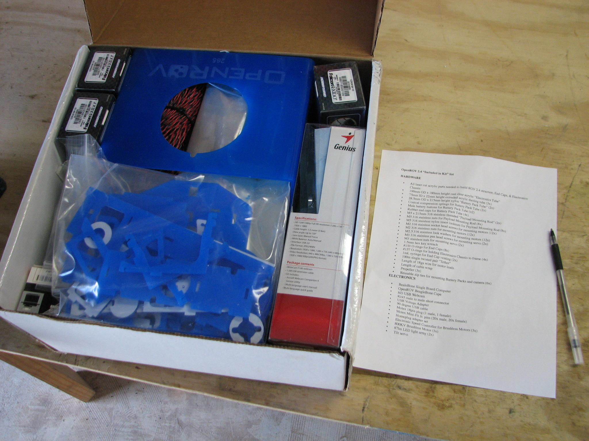
Starting Inventory, Bag Of Some Acrylic Pieces On Top
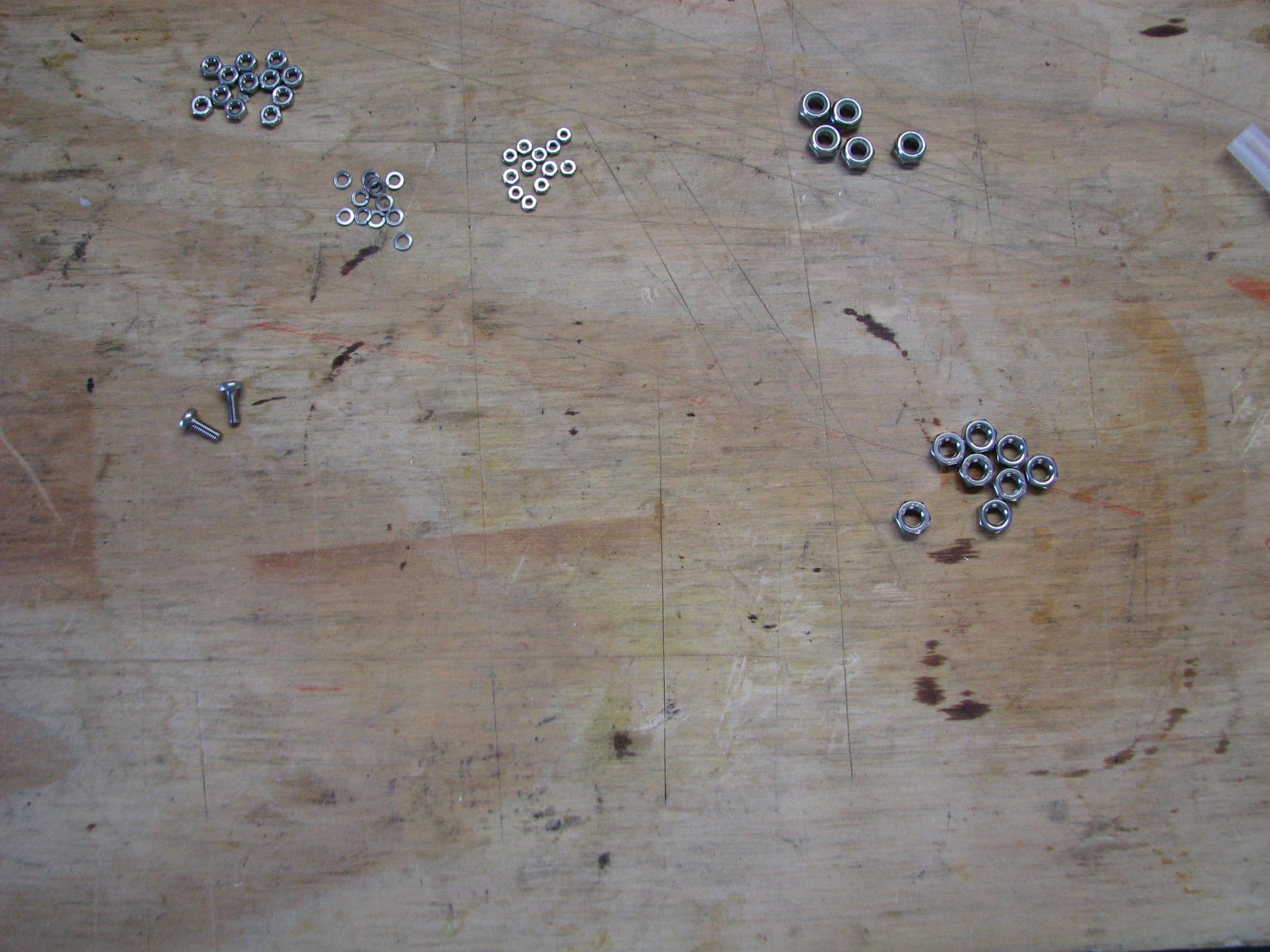
Bolts & Nuts Being Inventoried
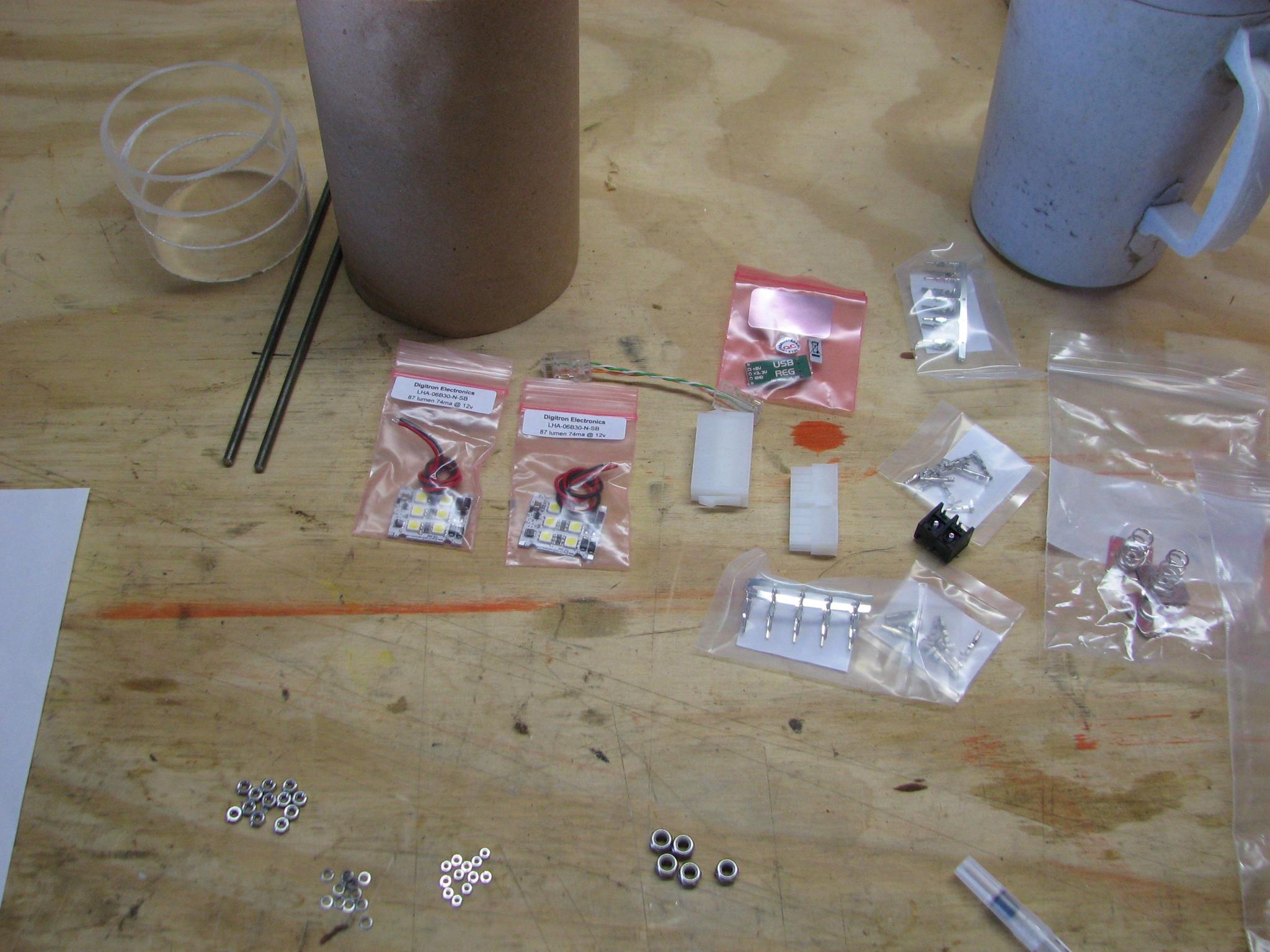
Various Parts Being Inventoried
Medialink Network Adapter
Now all that remains is
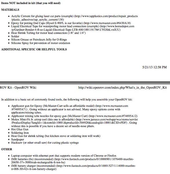
to order, or verify I have the parts and tools not in the kit.
Items Not In The Kit That Will Be Needed
Stacy has made plans to
come to Delcambre over the Memorial Day weekend, so we will get our
OpenROV kit together then.
May 01, 2013, Wednesday
Went through the kit
and it looks very complete, but did not have the “What’s
In the OpenROV Kit” with
me when I did this. I have a bunch of photos of all of the stuff, but
I still have to do not have a proper inventory. Please enjoy the
photos.
First Group Of Parts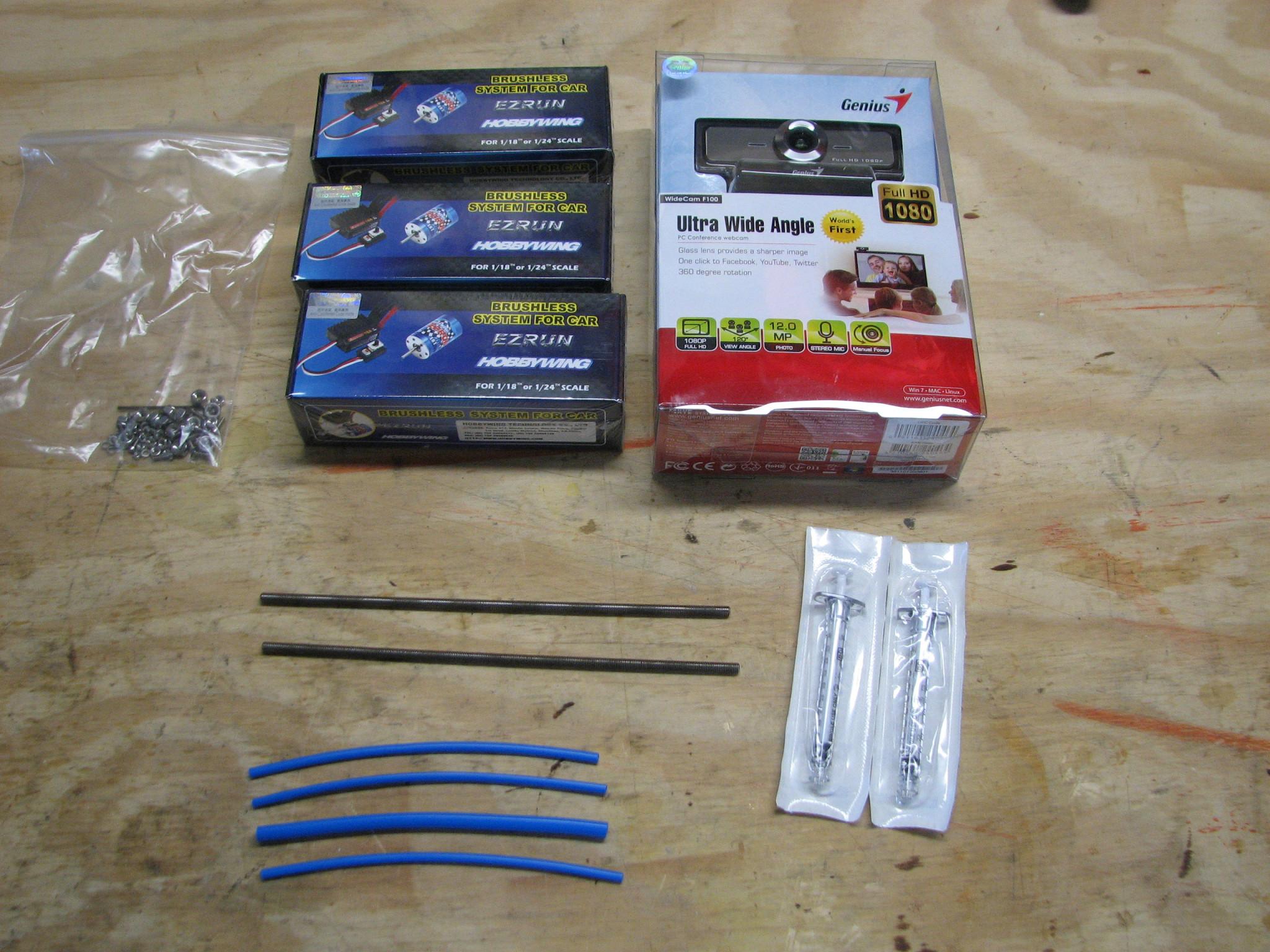

Second Group Of Parts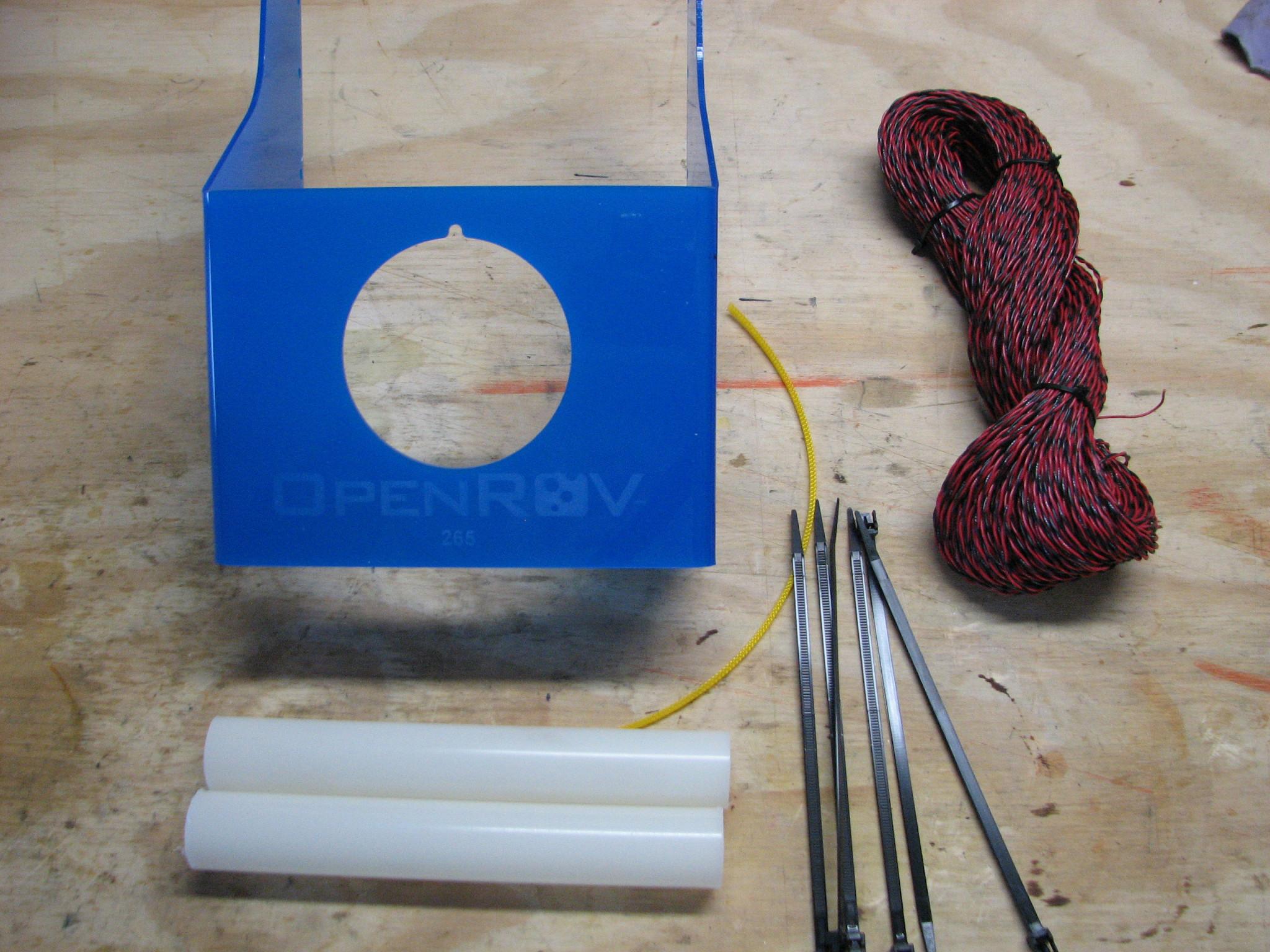

Third Group Of Parts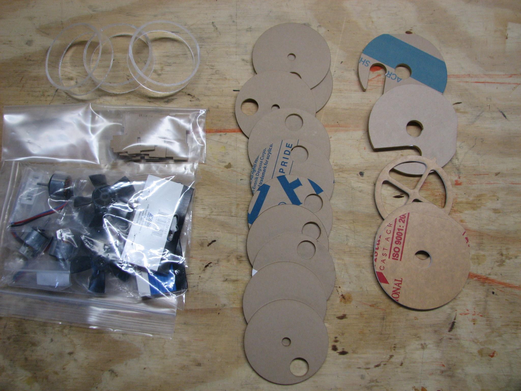

Fourth Group Of Parts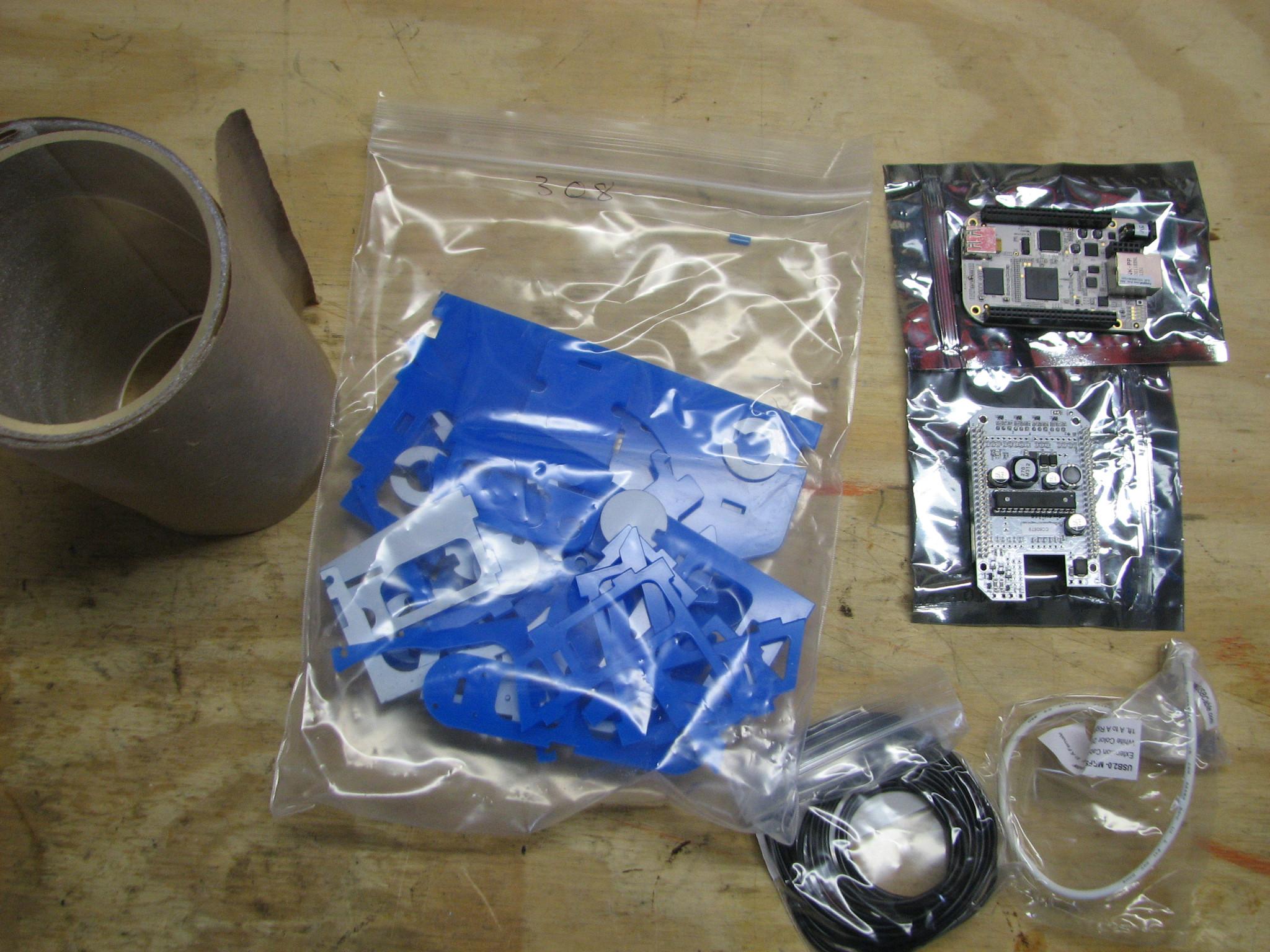

BeagleBone Computer And
BeagleBone Cape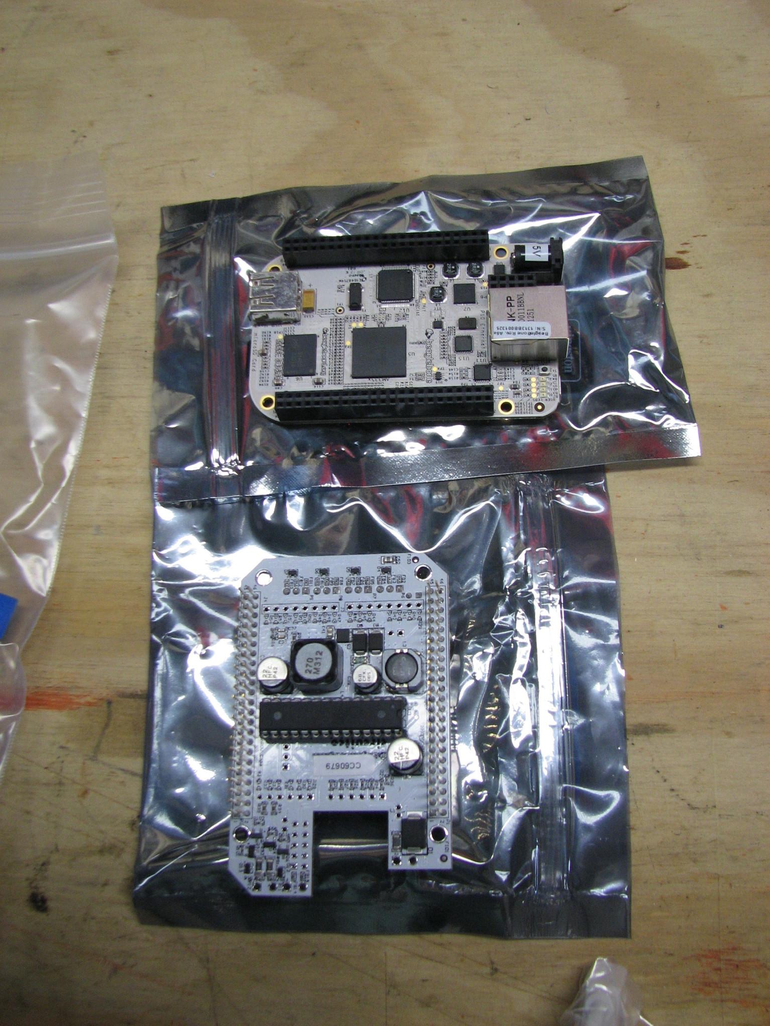

Fifth Group Of Parts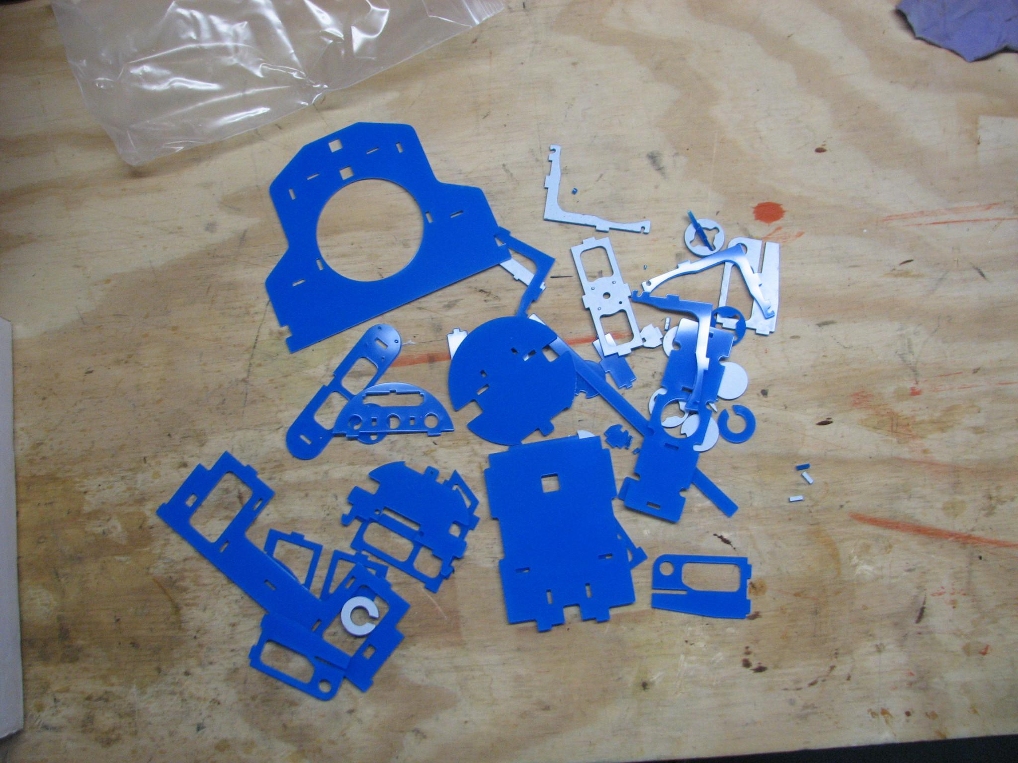

Sixth Group Of Parts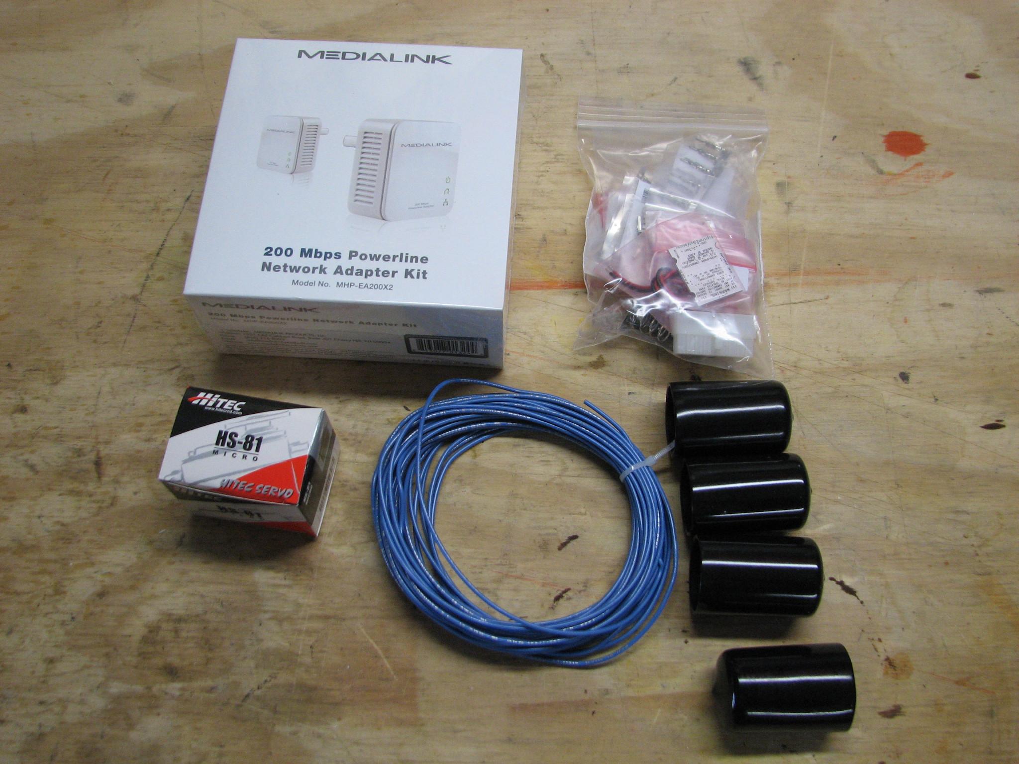

All Parts Back In The
Box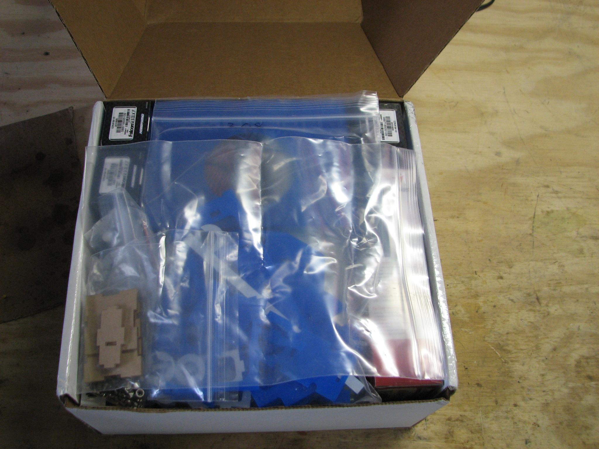

As you can see, lots of
small parts to assemble. Of course in the documentation, they say it
can be put together in a weekend. Probably something like a two hour
boat project that takes four days. I also wonder if they are talking
a 48 hour weekend, or just two eight hour days?
When Stacy and I get
together, we will find out!!
April 29, 2013, Monday
Stacy found the
OpenROV
web site last year at the beginning of December. It is a really cool
innovation, and we perceive it has many practical uses, especially if
you live aboard a sailboat. The need to explore the underwater
surroundings is self-evident.
Stacy and I talked
about the device, and decided we should attempt to build a unit for
testing. By the end of December of 2012, the
OpenROV
group were selling
kits. Stacy and I
immediately ordered one. That was the good news. The bad news was our
order arrived at the company after they had already sold out of the
first run of the units. So, we got in on the second build of kits,
with a scheduled delivery for April of 2013. The good news is there
were many changes and upgrades made from the original run of kits, so
we were actually getting a better kit than the first run.
And now the moment of
truth has arrived. I received an email from the
OpenROV
group last week telling me to be on the lookout for our kit delivery.
Today, April 29th, the kit arrived. Now Stacy has to schedule some
time to come to Delcambre so we can put the kit together, and test
it.
Welcome Letter To The
OpenROV
Community

Kit On Shop Work Bench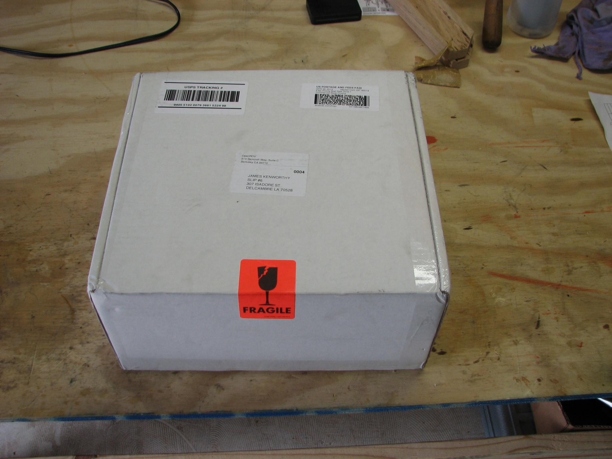

Kit Contents And
Welcome Letter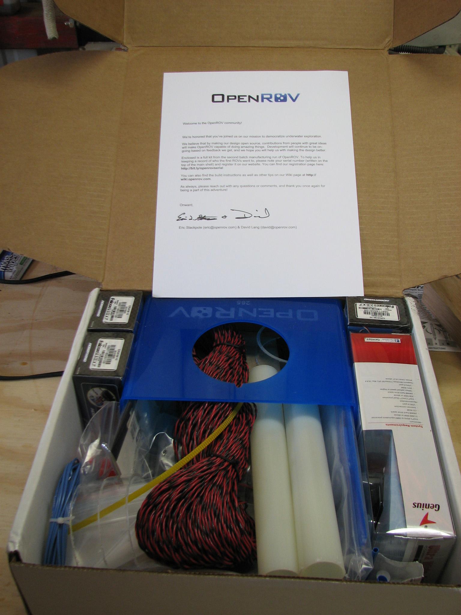

Close Up Of Kit
Contents, Kit #265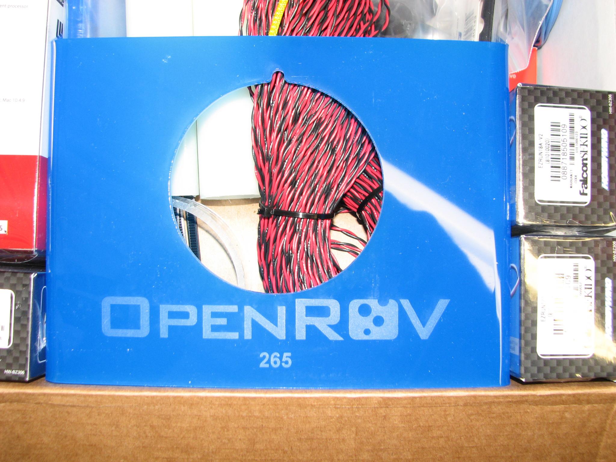

More Kit Contents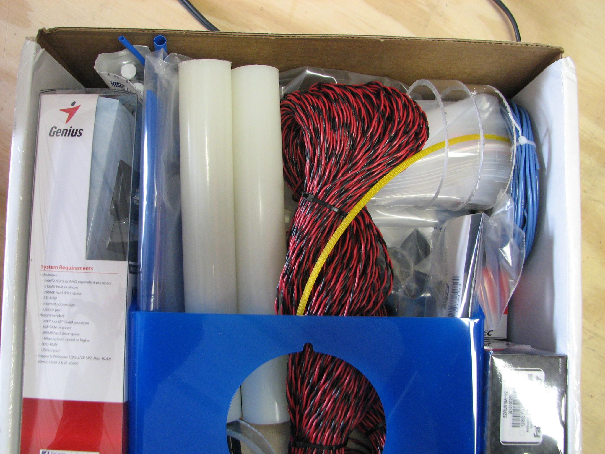

More Kit Contents

More Kit Contents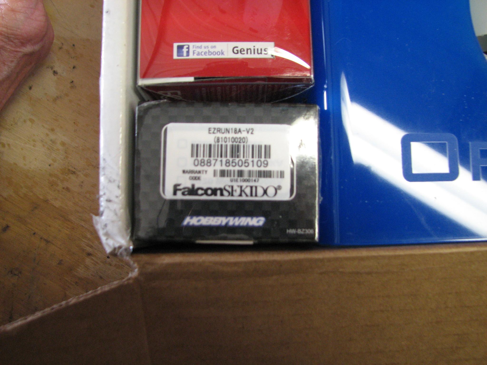

I did not actually take
any of the kit parts out of the box. I was afraid I would never get
them all back in the box. Tomorrow, April 30th, I will find a larger
box than the kit box, and inventory the contents.